TPC LASER MANUAL
3/01/07 Valid for Run 7
Alexei Lebedev & Blair Stringfellow
1.0 Turning on the Lasers
There are two TPC lasers (east & west) which are used for calibration. The same two lasers are used by the FTPC (the beams are steered remotely into either chamber).
NOTE: FTPC laser runs are to be performed by experts only – they require laser steering.
For the TPC, laser runs should be taken ~ one hour after the start of a store and ~every 3 to 4 hours afterward (for as long as the store lasts.). A laser run should be a dedicated DAQ run of at least 2000 events. Check the Panitkin plots online for the automatically calculated drift velocity.
For the TPC laser runs:
1. STOP the current DAQ physics run.
2. Turn on the WEST laser AC power as follows:
(The WEST laser overheats if the AC power is left on between runs.)
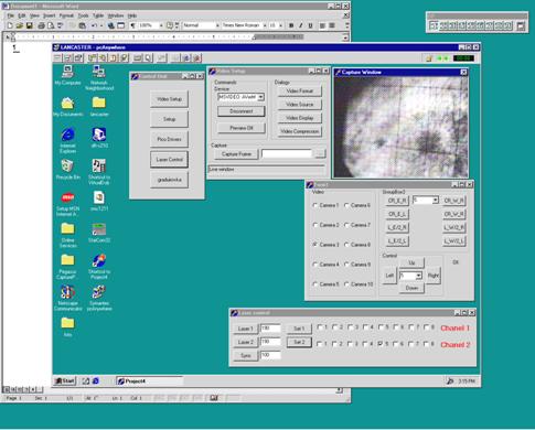
A. Go to the laser CCD control panel which is displayed on the PC TPClaser.starp.bnl.gov in the control room. If the CCD control panel is not displayed, see below for instructions to get it started.
B. Click on the “ #3” box in the channel 2 row on the CCD control panel. Then click on the “Set 2” button. (See picture below.)
![]()
![]()
Set 2 button # 3 box
NOTE: In the following procedure, it is necessary to start both lasers together. The controls will not work for one laser only.
To turn on the lasers:
3. Go to desk top # 5 on Chaplin ( TPC control computer) and click on the “Laser” button to bring up the laser control panel. Make sure the sliders for “Laser Pause Time”, “Data Enable Time” and “Laser Run Time” are slid fully to the right.
 |
4. Click on the sequence on “ON” button and within a few seconds, click on the “Unit 1 On” and Unit 2 On” lamp power buttons. The lasers should come up to full power within 2 minute. Note that only the EAST laser will trigger DAQ. When the lasers are on, the display will look like:
 |
5. To check that the lasers are really on, see below for a method to view the laser spot via CCD camera.
6. Wait ~ 5 minutes for the lasers to come to full power.
7. Start a DAQ laser run with ONLY DAQ, Trigger and TPC in the run. DAQ should run at ~ 10 Hz.
8. After the run, turn the lasers off by clicking on “Unit 1 Off”, “Unit 2 Off”, and the Sequence “OFF” button in turn. Wait until the “Lasers Standing By” message appears in the left hand box. Then, turn the WEST laser AC power off by clicking #3 box and “Set 2” on TPClaser.
2. Viewing the laser control boxes on the platform
Using the STAR plant remote TV system one can view the status lights on the laser control boxes on the south platform. To do this, go to the conventional systems PC (upper right monitor at the magnet control console). The TV system should be running, but may be hidden by the water system readouts. To get the TV image up, click on the iconized button labeled “Image Pull – Microsoft Internet Explorer”. To get the camera controls up, click on the iconized button labeled “VIDEOPC – pcAnywhere”. If the TV system is not running, see below to get it started or consult the manual which is in the holder on the right side of the cabinet.
To view the control boxes, do the following:
1. On the camera control window, select camera “First Floor”.
2. Click on #1 for the WEST laser control box or #2 for the EAST control box. (The row of numbered buttons are preset camera positions.) The picture should look like:
 |
This shows the control box with the “OFF” light lit. After turning the lasers on, the picture should change to:
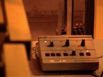 |
The lower right light is the “ON” light. The upper left is the “Lamp Sync” light. If these two lights aren’t on, the laser is not functioning properly.
If the STAR remote TV system is not running on the conventional systems PC, do the following:
1. Double click on the desktop icon labeled “Symantec pcAnywhere”. The pcAnywhere window will come up. Select the icon "VideoPC" and double click on it.
2. Logon to VideoPC – Username:BRANDIN, Password:ANDREY
3. This will bring up the VIDEOPC desktop with the remote camera controls visible. To avoid confusion you can drag and shrink the window until only the camera controls are visible (STAR Video System).
4. Back on the conventional systems PC, click on the icon labeled “VideoPC”. This will bring up a local Microsoft Explorer session that displays the remote camera images. More detailed instructions for this system can be found in the plastic holder to the right of the conventional systems montor.
3. Viewing the laser spots
A separate remote CCD system allows one to view the East & West laser spots. To view these CCD’s:
1. Go to the PC TPClaser.starp.bnl.gov near the TPC control computer.
2. On the desktop, double click on the icon “Symantec pcAnywhere”. After the program starts, doubleclick on the “TPC laser” icon.
3. Login using Username:BRANDIN, Password:ANDREY.
4. This brings up the controls on the TPClaser desktop as shown:
 |
5. In the “FORM1” window, the various CCD cameras can be selected, as follows:
Cameras 1 & 2 = West laser aimed at TPC
Cameras 3 & 4 = East laser aimed at TPC
Cameras 5 & 6 = West laser aimed at FTPC
Cameras 7 & 8 = East laser aimed at FTPC
Cameras 9 -16 = SMD gas bubblers.
CAUTION: Do not click on any other controls in the form 1 window, or in the “control unit” or “Video setup” windows.
When the lasers are running, a somewhat synchronized bright spot should be visible on the appropriate CCD camera. Lack of a spot usually means the laser is not working.
4. Steering the lasers to the FTPC & Back
NOTE: The following is for EXPERTS ONLY
The same lasers service both the TPC and the FTPC, but not simultaneously. To steer the beams from the TPC to the FTPC:
1. In the “laser control” window, click on the windows labeled 1 and 2 in the row labeled “Chanel 2”
A check mark should appear in each window. Then click on the “Set 2” button. This sends a TTL pulse that controls flippers on the platform. Window 1 is for the east laser, 2 is for the west laser.
2. To check that the beams are now steered to the FTPC, check for the laser spots on cameras 5 & 6 (West laser) and cameras 7 & 8 (East laser)
3. To steer the lasers back to the TPC, click on the boxes 1 & 3 again. The check marks should disappear. Then click on the “Set 2” button.